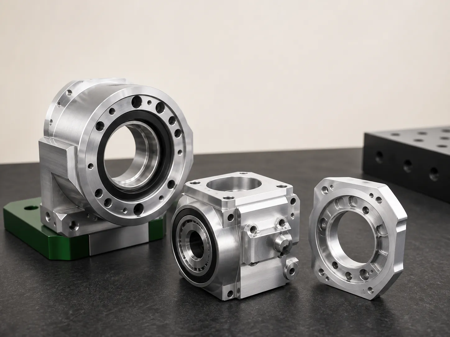
JOINT & ACTUATOR
Bearing seats, motor faces and gearbox patterns.
Control coaxial relationships, fit classes, runout, wall thickness and mounting datums as one released interface.
Review this family Factory liveSend drawing
 01 ROBOTICS & AUTOMATION
A robot component is only useful when its bearing seat, motor face, gearbox pattern and mounting datums work together. We review the complete feature relationship before quotation.
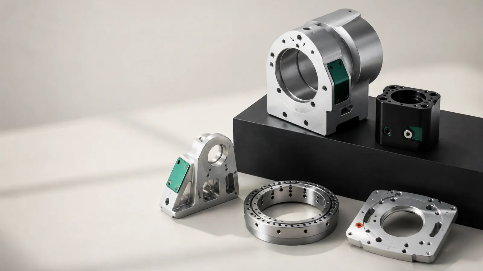
02 ROBOT PARTS · FACTORY PROOF
A concise factory view of the controls that matter in robot structural parts: bearing seats, motor pilots, bolt circles, datums and inspection records.
RFQ FAST FIRST CONTACT
Drawing upload is optional. Engineering can request the controlled file securely.
02 PART FAMILIES
Each family has a different risk stack. The page separates them so sourcing and engineering teams can identify the correct manufacturing conversation.
Control coaxial relationships, fit classes, runout, wall thickness and mounting datums as one released interface.
Review this family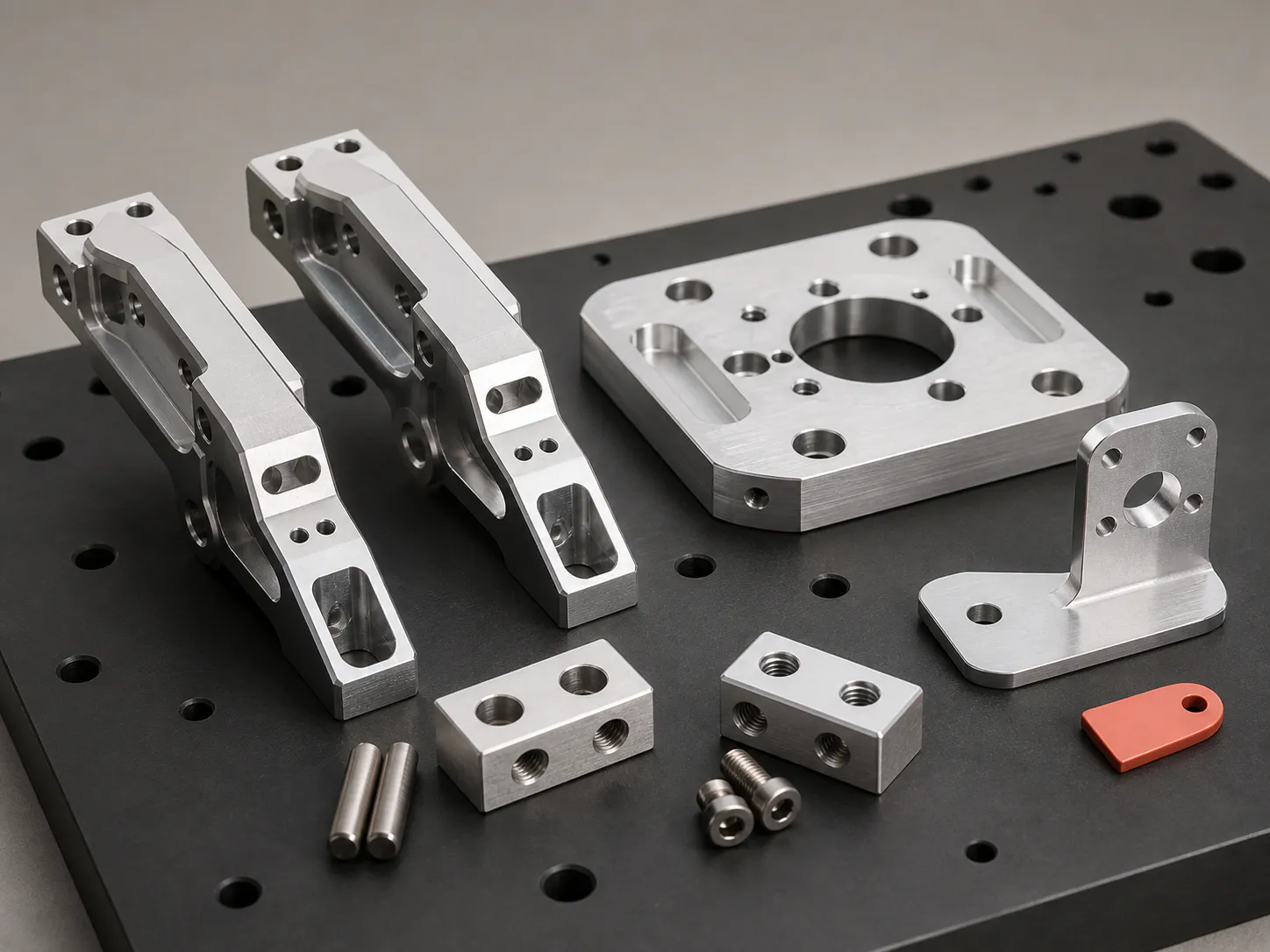
Machined around repeatable location, load path, reach, cable clearance and service access.
Review this family03 FEATURE CONTROL
Seat diameter, roundness, surface condition and coaxial relationship.
Pilot, bolt circle, face runout and assembly access.
Repeatable location through prototype, fixture and inspection.
Pocketing, wall thickness, ribs and load path defined by the drawing.
Anodize, masking, conversion coating and functional surfaces separated.
05 FACTORY EVIDENCE
Certificate and assessment scope must be verified against the legal entity, manufacturing site and project.
Request remote factory auditIncluded: drawing-defined housings, plates, brackets, flanges, gripper fingers and interface parts. Excluded unless separately confirmed: motors, bearings, gearboxes, electronics, wiring, controls, complete assembly and product design.
06 DIRECT ANSWERS
KEC Tour supplies drawing-defined metal structural parts such as joint and actuator housings, motor and gearbox interfaces, bearing-seat bodies, end-effector plates, gripper fingers, sensor brackets and automation mounting hardware.
A STEP or STP model plus the controlled PDF drawing is preferred. Identify datums, fits, bearing seats, mating patterns, material, finish, quantity and inspection requirements.
The standard offer covers custom machined metal components only. Motors, bearings, gearboxes, controls, wiring, complete assembly and product R&D are outside scope unless separately confirmed in writing.
Inspection follows the released drawing and may include CMM reports, bore and bearing-seat measurement, positional checks, flatness, runout, thread gauges and material documentation.
READY FOR A MANUFACTURING REVIEW?