Geometry
Bores, threads, cross-holes, radii, grooves, shoulders, wrenching and accessible tool paths.

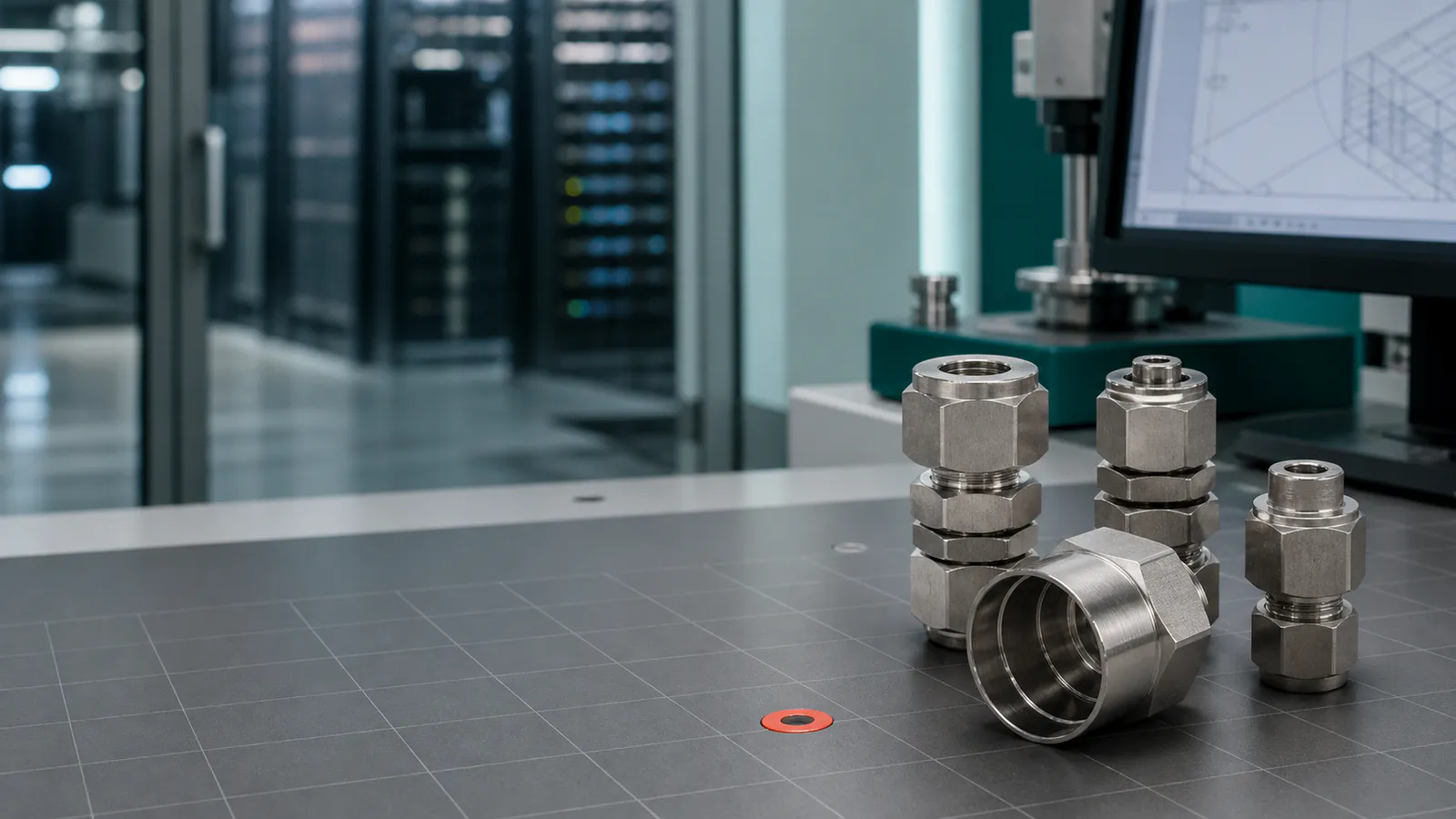
LIQUID-COOLING HARDWARE / 09
Send the controlled geometry—not just the connector name. KEC Tour reviews bores, threads, sealing faces, grooves, datum relationships, material, finish and inspection evidence before quotation.
FAST FIRST-CONTACT RFQ
PART-FAMILY ROUTING
Part names help route an enquiry. The quote becomes useful when the drawing defines how the part mates, locates, seals, routes flow and can be measured.
Drawing-defined male, female and bulkhead bodies with controlled bores, threads, grooves, shoulders and wrenching features.
Straight · angled · panel-pass-throughReview this part familyCustom transitions between customer-specified tube, hose, thread and equipment-side interfaces—machined to the released geometry.
Elbows · reducers · unions · standoffsReview this part familyCompact ported blocks and distribution interfaces where location, orientation, datum control and access define the manufacturing risk.
T-bodies · port blocks · custom interfacesReview this part familyPrecision turned and milled hardware that locates, retains or protects a customer-controlled connector or cooling assembly.
Sleeves · nuts · collars · ferrule hardwareReview this part familyINTERACTIVE FLOW-AXIS VIEW
Move across the real KEC Tour product image for a depth view. The annotations show the review logic; quotation still follows the customer-controlled model and drawing.
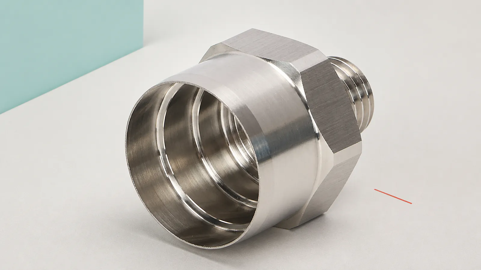
SPECIFICATION MAP
The graphic is a review sequence, not a performance rating. Each layer resolves a different source of manufacturing uncertainty before release.
Bores, threads, cross-holes, radii, grooves, shoulders, wrenching and accessible tool paths.
Mating part, datum scheme, locating faces, port orientation, assembly access and sealing concept.
Customer-specified alloy, corrosion context, surface treatment, cleanliness and cosmetic zones.
Critical characteristics, gauges, sampling, reports and material documentation agreed in advance.
MOTION EXPLAINS THE PART
The dedicated film is built from raw KEC Tour production footage: material preparation, active CNC turning, feature inspection and release verification, with restrained engineering overlays.
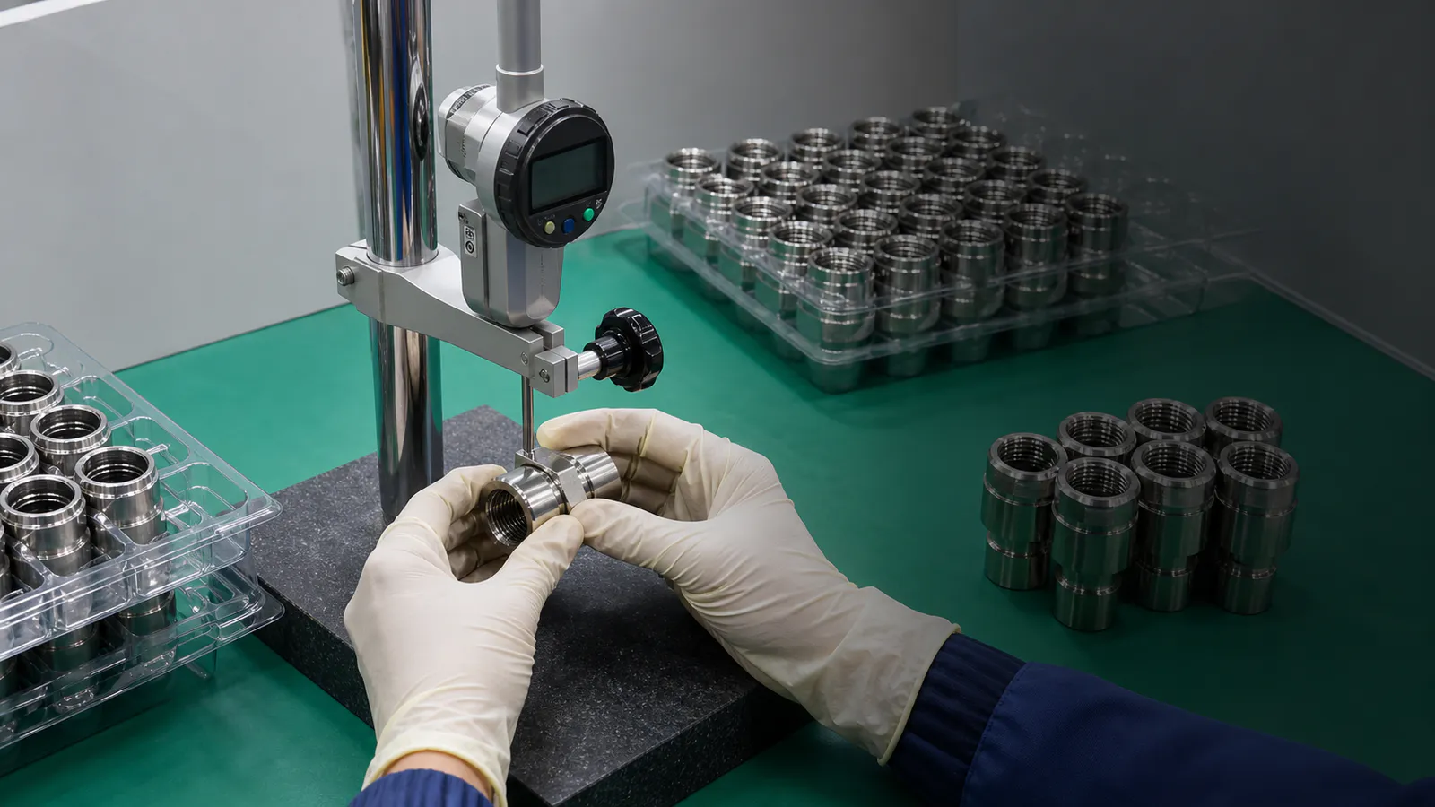
EVIDENCE BEFORE RELEASE
Not every characteristic needs the same method. The inspection plan should follow the features that control fit, orientation, retention and sealing geometry.
DRAWING-TO-PART ROUTE
The route separates manufacturing review from system-level validation. Your engineering team retains control of application requirements and final approval.
Drawing, mating geometry, material and critical characteristics.
Machining sequence, access, workholding and finishing considerations.
Methods and evidence aligned with functional risk and access.
Approved revision, controlled records and repeat-order reference.
SCOPE CLARITY
TECHNICAL FAQ
Clear early answers protect both the quotation and the released part.
Customer-designed metal connector bodies, elbows, adapters, unions, bulkhead fittings, port blocks, sleeves, collars, nuts and related drawing-defined cooling-loop hardware. Complete cooling systems, pumps, electronics and certified connector products are outside the standard scope unless separately verified in writing.
Send a STEP or STP model with the controlled PDF drawing when available. Identify the mating interfaces, thread or tube standard, sealing concept, material, surface finish, critical dimensions, quantity, inspection evidence and target timing.
Material and seal compatibility remain application decisions controlled by the customer or system designer. KEC Tour can manufacture the released metal geometry and review drawing-defined material and finish requirements, but does not make an unqualified fluid-compatibility or system-performance claim.
The method follows feature access, tolerance and functional risk. Evidence may include thread gauges, bore measurement, concentricity or runout checks, optical or CMM inspection, surface-finish verification and material documentation as agreed before production.
Yes. A project can start with prototypes or a validation lot, then move to bridge or repeat production after the drawing, process route, fixturing and inspection controls are released.
READY FOR MANUFACTURING REVIEW?
Upload now or start with the three required contact details. Engineering can request the controlled files securely.