
Burr Direction on Stamped Parts: Put the Functional Edge on the Drawing
Specify the acceptable edge condition and orientation where stamped parts contact seals, wires, hands or mating surfaces.
 Zaid ArshadManufacturing Content Author · KEC Tour
Identify which edge matters
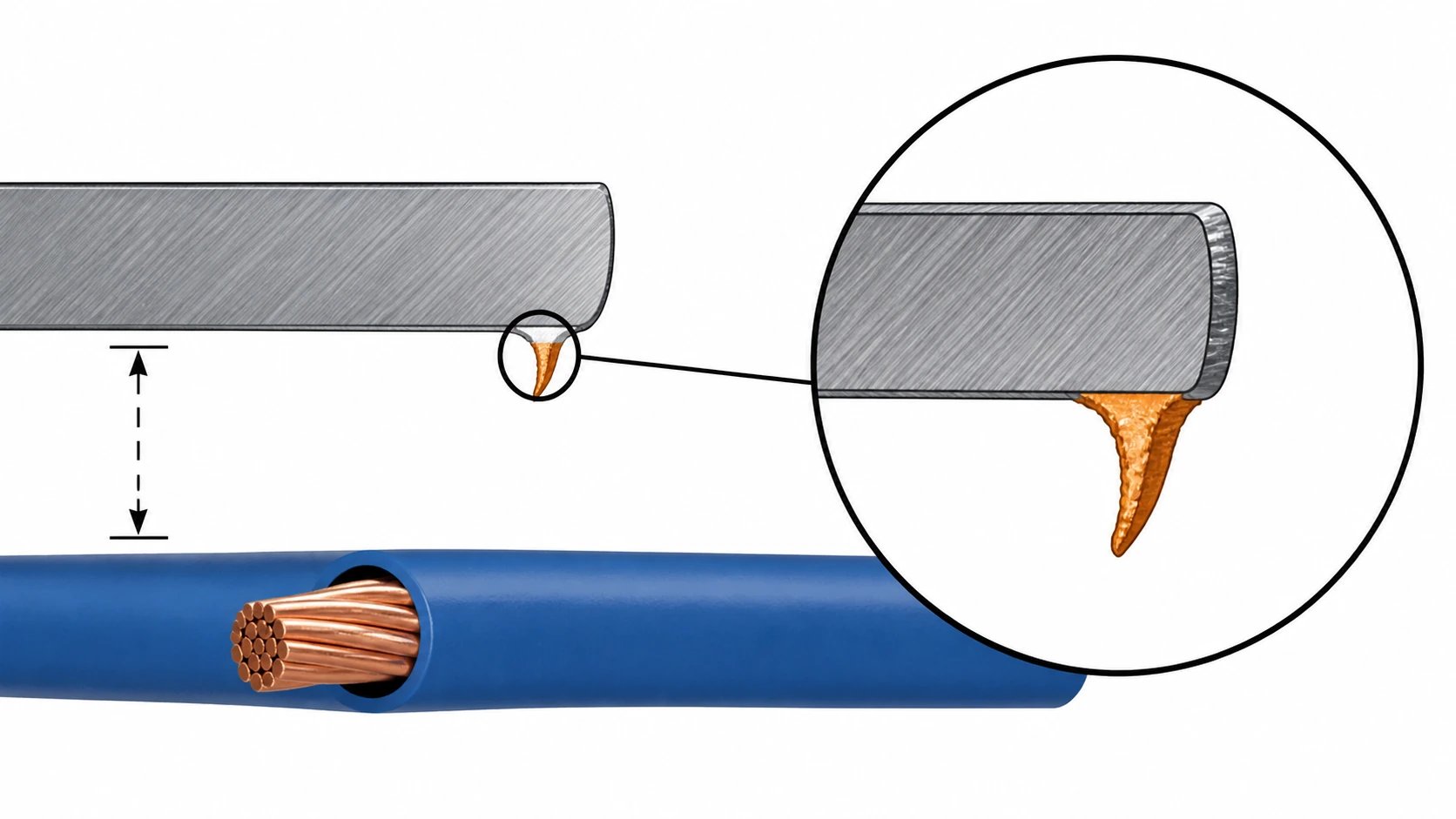
A stamped edge can affect handling, assembly, coating and contact with a neighboring component. Mark the regions that touch a seal, cable, sliding surface or user-accessible area. The required control should follow that function. A blanket burr note can either miss a critical orientation or impose unnecessary work on edges that have no comparable requirement.
Separate direction from size
The side on which a burr appears and the amount of burr are different characteristics. Define the required orientation using an unambiguous drawing view or identified face. Where necessary, state a measurable limit and inspection method. Avoid subjective requirements such as “small burr” because different inspectors may accept different edge conditions while believing they are following the same drawing.
Review tooling and forming sequence
Blanking direction, tooling condition and subsequent forming can affect where the finished edge is presented to the assembly. Discuss the process sequence with the stamping supplier before freezing orientation-sensitive features. A part that is flipped during a later operation can place the burr on the wrong functional side. Ensure the work instruction and fixture prevent that reversal or provide a reliable check.
Validate any secondary edge treatment
Brushing, tumbling or another finishing operation can change dimensions, corner condition and appearance as well as the burr. Confirm that the selected route reaches the critical edge without damaging thin tabs or decorative surfaces. Inspect after the last operation that can alter the edge. If the part is coated, determine whether coating hides the defect visually without removing its functional effect.
Connect wear checks to the edge requirement
Tool wear can change edge quality over a run. Include suitable setup and production checks in the control plan, with a reaction rule for approaching or exceeding the specified limit. Keep samples or images when they improve consistent interpretation. If a mating component is damaged in assembly, examine the edge orientation and actual contact path as well as the measured burr size.
Approval checklist and evidence
| Review item | Decision to make | Evidence to retain |
|---|---|---|
| Contact path | Mark edges near cables, seals or sliding surfaces. | Functional drawing view identifying the affected face. |
| Orientation | Specify which side may contain the accepted burr. | Unambiguous face reference and manufacturing sequence. |
| Edge treatment | Validate removal without damaging other part features. | Final-condition edge and dimensional inspection. |
| Wear control | Detect changes during the production run. | Setup and interval checks with a defined reaction. |
Worked review example
Illustrative scenario: a stamped bracket meets its outline dimensions but scratches a cable jacket because the burr faces the cable route. The drawing previously controlled only overall size. The revision identifies the cable-contact edge, specifies its accepted condition and fixes the orientation in the manufacturing and assembly instructions. The supplier validates the treatment on that edge rather than applying a cosmetic finish to the broad faces alone.
Information for the engineering review
- Functional edge and contact path
- Identified burr side
- Measurable edge requirement
- Forming and finishing sequence
- Tool-wear checks and reaction rule
Discuss this requirement with KEC Tour using the controlled drawing, the relevant mating interfaces and the review information above. Identify the decision that needs confirmation and the acceptance evidence expected with the first parts.
Sources and further reading
Frequently asked questions
Can paint eliminate a sharp burr?
Do not assume so. Inspect the underlying functional edge and final condition.
Should every stamped edge be rounded equally?
Only where the design requires it. Edge treatment can affect dimensions and mating behavior.

Zaid Arshad
Manufacturing Content Author · KEC TourZaid Arshad writes practical manufacturing guides for engineers and sourcing teams evaluating custom fittings, CNC-turned parts, sheet-metal components, stampings and die-cast parts. His articles focus on clearer RFQs, supplier evidence, inspection planning and drawing-to-production decisions.
View author profileRelated engineering guides

Engineering Changes for Custom Metal Assemblies: Control the Cutover
Link revised drawings, purchased parts, work in progress and inspection so a design change reaches the correct production units.
Read article
Die Casting Porosity in Leak-Critical Parts: Plan Before Tooling
Connect casting design, machined surfaces, inspection and leak acceptance before committing to a pressure-containing part.
Read article
How to choose stainless steel grades for non-standard fittings
A practical guide for balancing corrosion resistance, machining stability, pressure use, surface finish, and cost.
Read articleTurn your requirements into a production-ready RFQ.
Share your CAD file, material, critical dimensions, finish and target volume. KEC Tour will review the process route before quoting.