
CNC-Machined Pressure Transmitter Housings: Design and RFQ Guide
Plan material, wall thickness, ports, datums, sealing interfaces and final inspection for a custom CNC-machined pressure transmitter housing.
 Zaid ArshadManufacturing Content Author · KEC Tour

What to specify for this part
| Control point | Define in the RFQ | Risk if omitted |
|---|---|---|
| Pressure interface | Port standard and sealing mechanism | A thread can pass a basic check but fail in assembly |
| Sensor seat | Datum, depth, flatness and surface condition | Sensor position or preload changes |
| Wall and transitions | Minimum wall, corner radius and cross-hole relation | Machining leaves weakness or burr traps |
| External interface | Connector, wrench flats, markings and finish | Assembly access or identification fails |
Build the datum system around function
Choose datums that represent how the housing seats and aligns in the final assembly. Dimension the pressure port, sensor seat and connector interface from those datums rather than chaining many local dimensions. For a housing with a sensor seat and pressure port, establish the seat plane and locating axis from the assembly. Chaining depth dimensions from several exterior faces can hide the functional stack. Use section views to make the relationship between the diaphragm region, seat and port explicit.
Control internal intersections
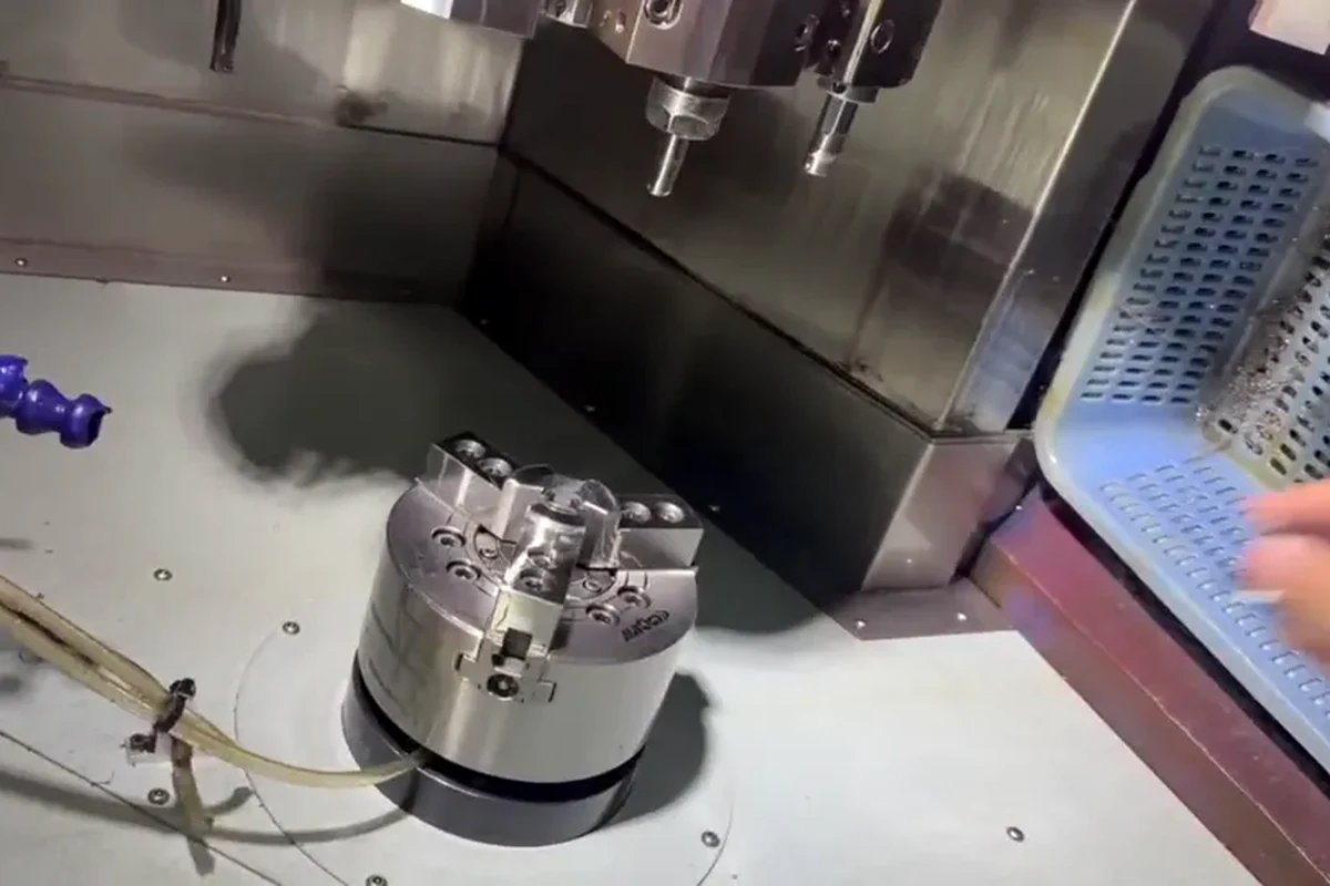
Deep bores and intersecting passages complicate tool access, chip evacuation and deburring. Provide section views and explicitly mark fluid passages that must be clean and free of loose burrs. Review drill approach and the sequence of intersecting bores before the toolpath is released. A burr behind a small port may be inaccessible to ordinary hand tools. Choose a process and inspection access that can demonstrate the passage is clear without relying on an exterior photograph.
Define material and finish as a system
Specify the exact stainless or aluminum grade and condition, then identify passivation, anodizing or other finish separately. Confirm whether dimensions and threads are accepted before or after finishing. A finish cannot substitute for a suitable base material or a validated pressure design. Mark areas where a treatment is prohibited or where dimensions apply after treatment. Confirm compatibility with the intended fluid through the product-design process rather than assuming that all stainless grades behave alike.
Make inspection evidence proportional to risk
A first-article report should cover functional characteristics, not every easy dimension while ignoring the pressure interface. Add material evidence and a defined functional test only when the application requires it. The customer must define pressure rating and qualification requirements for the application. Manufacturing inspection should then verify the specified interfaces, wall constraints and approved test requirements. A machined housing without those approvals should not be described as a pressure-certified assembly.
Frequently asked questions
Is 304 or 316 stainless better for every housing?
Neither is universally better. Select using media, environment, strength, corrosion and regulatory requirements; name the exact grade on the drawing.
Can a supplier design the pressure rating?
The buyer or qualified design authority should define and validate application requirements. A machining supplier can provide DFM feedback but should not silently assume design responsibility.
What files speed quotation?
A STEP model, controlled 2D drawing, port standard, material, finish, quantities and inspection/test requirements.
Should all internal surfaces be tightly finished?
Only specify texture where it affects sealing, flow, cleaning or sensor function. Unnecessary requirements increase time and cost.
Sources and further reading
Send KEC Tour the relevant drawing and interface requirements for review of the proposed manufacturing route.

Zaid Arshad
Manufacturing Content Author · KEC TourZaid Arshad writes practical manufacturing guides for engineers and sourcing teams evaluating custom fittings, CNC-turned parts, sheet-metal components, stampings and die-cast parts. His articles focus on clearer RFQs, supplier evidence, inspection planning and drawing-to-production decisions.
View author profileRelated engineering guides

Engineering Changes for Custom Metal Assemblies: Control the Cutover
Link revised drawings, purchased parts, work in progress and inspection so a design change reaches the correct production units.
Read article
Burr Direction on Stamped Parts: Put the Functional Edge on the Drawing
Specify the acceptable edge condition and orientation where stamped parts contact seals, wires, hands or mating surfaces.
Read article
How to choose stainless steel grades for non-standard fittings
A practical guide for balancing corrosion resistance, machining stability, pressure use, surface finish, and cost.
Read articleTurn your requirements into a production-ready RFQ.
Share your CAD file, material, critical dimensions, finish and target volume. KEC Tour will review the process route before quoting.