
CNC Turning Tolerances for Sleeves, Bushings and Threaded Hardware
Plan turning tolerances around functional fits, wall stability, datum relationships and inspection for sleeves, bushings and threaded hardware.
 Zaid ArshadManufacturing Content Author · KEC Tour

What to specify for this part
| Control point | Define in the RFQ | Risk if omitted |
|---|---|---|
| Fit | Mating shaft and operating clearance/interference | A nominal bore does not define assembly |
| Axis relationship | Runout, concentric function or position | Separate diameters pass but rotate poorly |
| Length stack | Shoulders, grooves and installed stack | Axial preload is wrong |
| Measurement | Gauge, CMM, air gauge or comparative method | Method uncertainty overwhelms tolerance |
Start from the assembly fit
Use the mating shaft, temperature, lubrication and operating load to define the functional clearance or interference. ISO 286 provides a standardized system for common linear-size tolerances and fits. Do not select a hole fit independently of the mating shaft limits. A 20.000 to 20.020 mm bore against a 19.980 to 19.990 mm shaft gives an illustrative clearance range of 0.010 to 0.040 mm. Whether that is acceptable depends on the assembly and service conditions.
Avoid redundant geometric controls
Choose datums that reflect mounting and rotation, then control only the relationships that matter. Multiple overlapping runout, concentricity and position requirements can create ambiguity and cost. Define the functional rotation axis before applying a runout requirement. Two diameters can each meet size yet be misaligned. Avoid adding duplicate controls that inspect the same function using incompatible datum setups.
Match measurement to the feature
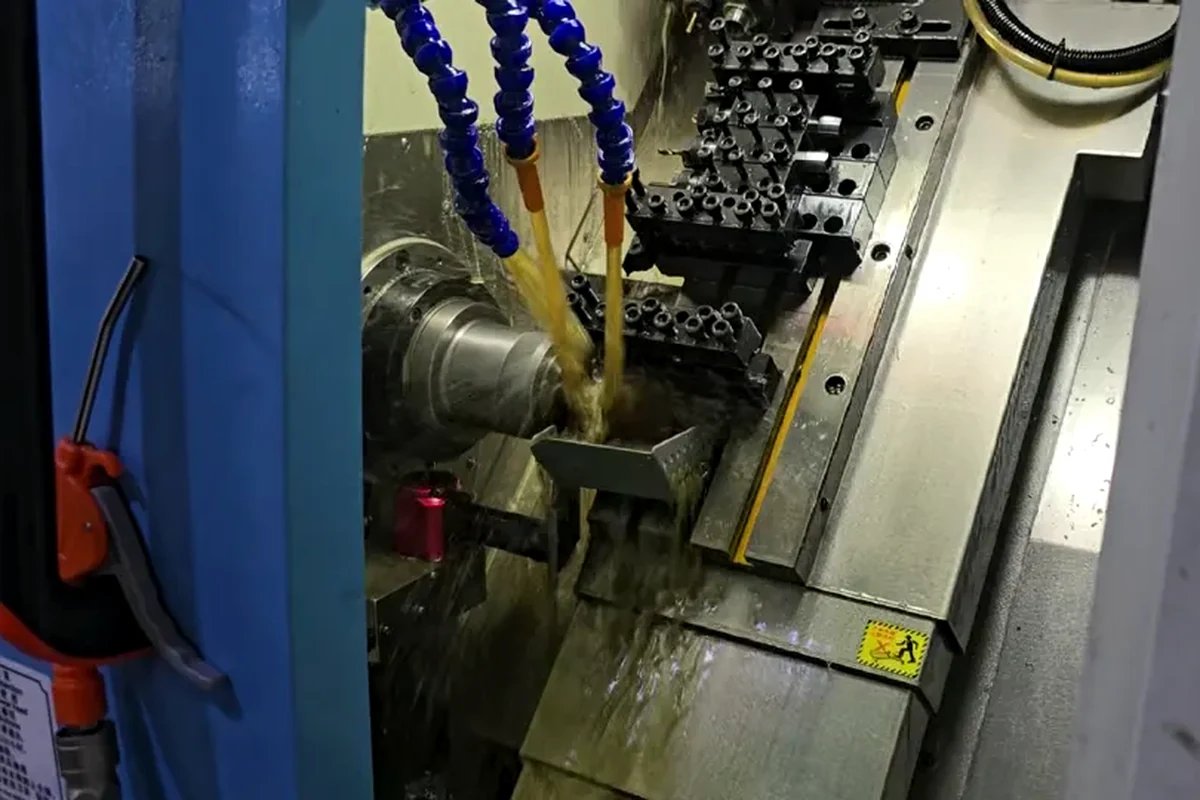
A micrometer, bore gauge, air gauge and CMM answer different questions. Agree the method for thin walls, interrupted bores and soft materials because clamping force and temperature can move the result. A thin sleeve may read differently while clamped and after release. Specify whether the drawing requires free-state geometry or a defined restrained condition. Correlate the production gauge with that acceptance setup before interpreting small differences as machining defects.
Prove capability before scaling
Measure first articles at controlled temperature, review the distribution rather than one passing result and lock the tool, offset, inspection frequency and reaction plan for production. Collect measurements through warm-up and a normal tool-change interval. A centred first piece does not prove the process stays centred over the entire batch. Define an action limit and the interval to hold when an in-process reading indicates loss of control.
Frequently asked questions
What tolerance can CNC turning hold?
There is no honest universal number. Diameter, length, material, wall thickness, geometry, temperature and inspection method all affect capability.
Is concentricity always needed?
Often runout or position relative to a functional datum communicates the requirement more directly; use the controlling drawing standard.
Why do thin bushings measure differently after unclamping?
Residual stress and chucking force can distort the part. The inspection fixture and free-state condition must match the requirement.
Should every production part receive a full report?
Usually critical features receive defined in-process or final checks; sampling and reporting should be agreed by risk and lot size.
Sources and further reading
Send KEC Tour the relevant drawing and interface requirements for review of the proposed manufacturing route.

Zaid Arshad
Manufacturing Content Author · KEC TourZaid Arshad writes practical manufacturing guides for engineers and sourcing teams evaluating custom fittings, CNC-turned parts, sheet-metal components, stampings and die-cast parts. His articles focus on clearer RFQs, supplier evidence, inspection planning and drawing-to-production decisions.
View author profileRelated engineering guides

Engineering Changes for Custom Metal Assemblies: Control the Cutover
Link revised drawings, purchased parts, work in progress and inspection so a design change reaches the correct production units.
Read article
Burr Direction on Stamped Parts: Put the Functional Edge on the Drawing
Specify the acceptable edge condition and orientation where stamped parts contact seals, wires, hands or mating surfaces.
Read article
How to choose stainless steel grades for non-standard fittings
A practical guide for balancing corrosion resistance, machining stability, pressure use, surface finish, and cost.
Read articleTurn your requirements into a production-ready RFQ.
Share your CAD file, material, critical dimensions, finish and target volume. KEC Tour will review the process route before quoting.