
Self-Clinching Fasteners in Sheet Metal: Design the Installation
Check sheet thickness, hardness, hole preparation, edge distance and installation access before specifying clinch hardware.
 Zaid ArshadManufacturing Content Author · KEC Tour
Select the exact fastener family
Self-clinching nuts, studs and standoffs use specific installation features and cannot be treated as generic threaded hardware. Select a manufacturer and part designation suitable for the sheet material and application. Obtain the current product data for that exact item. The required hole, sheet thickness, hardness and installation dimensions should come from the selected product, not from a similar-looking fastener found in a previous assembly.
Check the receiving sheet
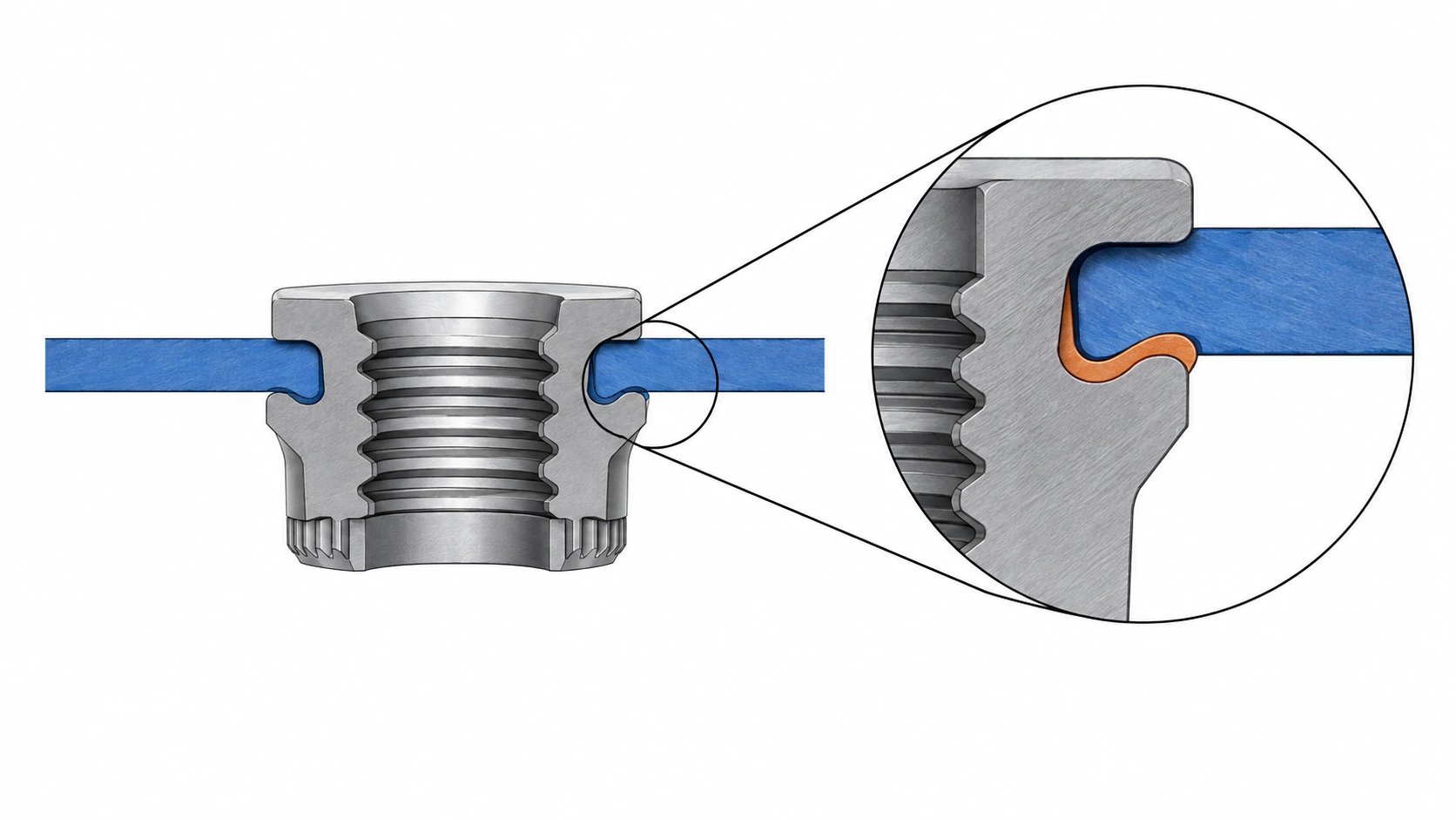
Clinch performance depends on the sheet being able to flow into the fastener’s retention features. Confirm thickness and hardness against the manufacturer’s limits, including the delivered material condition. A harder sheet or a thinner region near a formed feature may not behave like the nominal stock. If coating or heat treatment changes the installation condition, agree the sequence with the fastener manufacturer and fabricator.
Prepare the hole as specified
Use the specified hole size and preparation. PennEngineering’s handbook cautions against deburring mounting holes on either side because the operation removes metal needed for clinching. This differs from the general edge-cleaning practice used on many machined parts. Keep fastener mounting-hole instructions explicit so a broad deburr-all-edges note does not override a product-specific installation requirement.
Provide edge and tool clearance
Check edge distance, spacing and access for the punch and supporting anvil. A hole may fit the fastener while the completed bend prevents installation tooling from reaching it. Review whether hardware should be installed before or after forming, and what that sequence does to the surrounding sheet. Nearby bends and cutouts can affect support, so evaluate the actual part rather than only a flat material coupon.
Validate installation and retention
Use the manufacturer’s installation guidance and suitable controlled equipment. Inspect seating and thread condition, then verify retention properties where the application requires them using an agreed method. A visually flush nut is not proof of sufficient torque-out or push-out performance. Record the approved fastener, sheet condition and process settings so substitutions or changes to the forming sequence can be assessed before release.
Approval checklist and evidence
| Review item | Decision to make | Evidence to retain |
|---|---|---|
| Receiving sheet | Confirm thickness and hardness for the selected fastener. | Current manufacturer limits and material condition evidence. |
| Mounting hole | Preserve the exact specified hole preparation. | Hole measurements and product-specific edge instructions. |
| Tool access | Check punch, anvil, bends and edge clearance. | Approved sequence using the actual formed part geometry. |
| Retention | Verify seating, threads and required installed strength. | Application-specific installation validation and traceability. |
Worked review example
Illustrative scenario: a shop deburrs every laser-cut hole before installing clinch nuts. The selected fastener’s instructions require the mounting-hole edge to remain in the specified condition, and the removed material reduces the intended retention. The correction is to align the drawing note, hole process and work instruction with the exact fastener specification, then validate the installation. Simply increasing installation force could damage the sheet without restoring the missing geometry.
Information for the engineering review
- Exact manufacturer and fastener code
- Sheet thickness and hardness
- Product-specific mounting hole
- Edge distance and press-tool access
- Seating, thread and retention checks
Discuss this requirement with KEC Tour using the controlled drawing, the relevant mating interfaces and the review information above. Identify the decision that needs confirmation and the acceptance evidence expected with the first parts.
Sources and further reading
Frequently asked questions
Can all mounting holes be chamfered?
No. Follow the selected fastener’s hole-preparation instructions.
Is hand hammering an equivalent installation method?
Use the manufacturer-approved process and equipment; uncontrolled impact is not an assumed substitute.

Zaid Arshad
Manufacturing Content Author · KEC TourZaid Arshad writes practical manufacturing guides for engineers and sourcing teams evaluating custom fittings, CNC-turned parts, sheet-metal components, stampings and die-cast parts. His articles focus on clearer RFQs, supplier evidence, inspection planning and drawing-to-production decisions.
View author profileRelated engineering guides

Engineering Changes for Custom Metal Assemblies: Control the Cutover
Link revised drawings, purchased parts, work in progress and inspection so a design change reaches the correct production units.
Read article
Burr Direction on Stamped Parts: Put the Functional Edge on the Drawing
Specify the acceptable edge condition and orientation where stamped parts contact seals, wires, hands or mating surfaces.
Read article
How to choose stainless steel grades for non-standard fittings
A practical guide for balancing corrosion resistance, machining stability, pressure use, surface finish, and cost.
Read articleTurn your requirements into a production-ready RFQ.
Share your CAD file, material, critical dimensions, finish and target volume. KEC Tour will review the process route before quoting.