
Sheet Metal Springback: Validate the Bend Before Freezing the Blank
Use material, tooling and representative bend results to control final angle and develop a reliable flat pattern.
 Zaid ArshadManufacturing Content Author · KEC Tour
Define the finished bend
State the finished angle, inside radius and the condition in which the part is inspected. Include the drawing convention so an included angle is not confused with a bend angle. Identify the functional dimensions that depend on the bend, such as mounting-hole alignment. The target is the released part after forming, rather than an assumed tool angle or an unverified flat-pattern dimension.
Record the material and tool combination
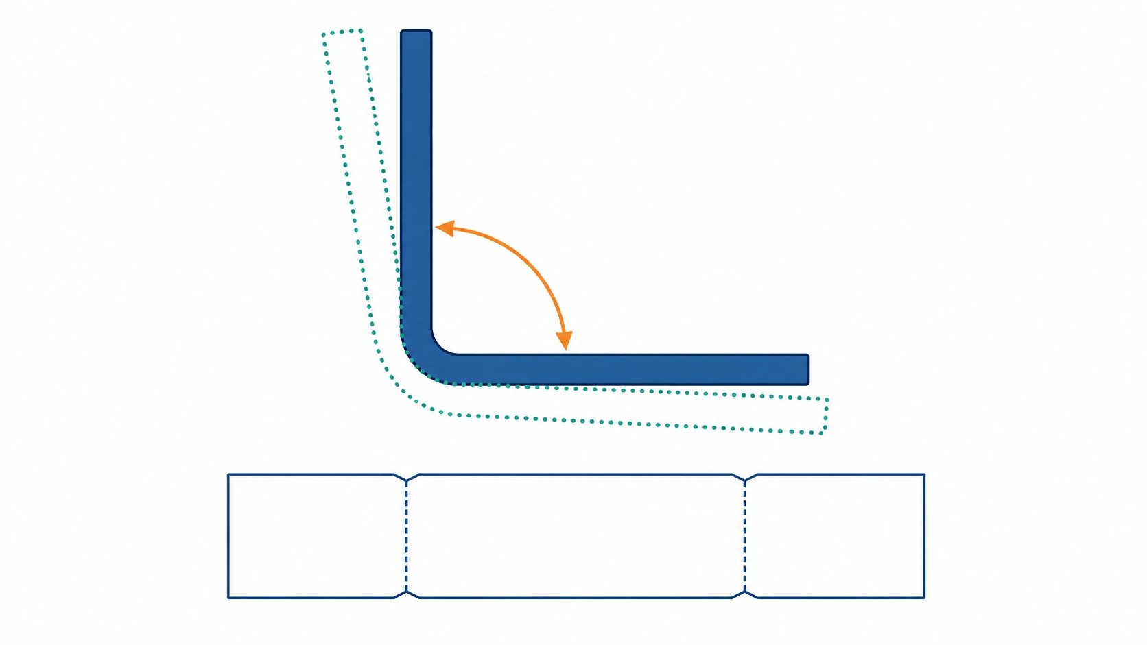
Springback depends on the material condition, geometry and forming process. Record thickness, grade, relevant grain orientation and the actual punch and die arrangement. A result from another material lot or tool opening may not transfer directly. Keep the trial record specific enough that the fabricator can reproduce the accepted route or recognize when a change calls for another validation.
Use representative bend trials
Make trial parts with the intended material and tooling, then measure after release using the agreed method. Determine the process adjustment needed to achieve the finished requirement. Avoid solving the production angle solely by changing the drawing nominal to match a convenient trial result. The designer owns the required geometry; the fabricator develops a controlled process capable of producing it.
Calibrate the flat-pattern assumptions
Bend allowance and deduction connect the blank to the formed dimensions. A generic K-factor can be a starting estimate, but the actual process should determine the value used for a critical part. Validate overall lengths and hole locations after forming as well as the angle. A correct angle with an incorrect allowance can still move mounting features out of position and prevent assembly.
Control production changes
Define checks at setup and suitable intervals to detect drift, tool changes or material variation. Record the accepted setup and final results in the manufacturing route. If the sheet grade, thickness, grain direction or tooling changes, assess whether the validated bend data still applies. Retain the approved flat pattern with its related formed drawing revision so old blanks are not mixed into a changed assembly.
Approval checklist and evidence
| Review item | Decision to make | Evidence to retain |
|---|---|---|
| Target geometry | Define finished angle and measurement convention. | Released drawing and agreed inspection condition. |
| Process inputs | Record grade, thickness, grain and actual tooling. | Representative trial record with reproducible setup details. |
| Blank development | Calibrate allowance using the intended forming route. | Final lengths and hole positions checked after bending. |
| Repeat production | Assess changed tooling or material before reuse. | Setup verification and controlled flat-pattern revision. |
Worked review example
Illustrative scenario: a bracket reaches its specified final angle after a press adjustment, but the distance between mounting holes remains wrong. The investigation separates springback compensation from the bend allowance used in the blank. Revising only the press setting cannot correct a length error introduced by the flat pattern. The team validates both angle and developed length with the intended tooling before releasing the new blank revision.
Information for the engineering review
- Finished angle and inspection convention
- Material condition and grain direction
- Punch, die and forming route
- Validated allowance and formed dimensions
- Setup checks and change triggers
Discuss this requirement with KEC Tour using the controlled drawing, the relevant mating interfaces and the review information above. Identify the decision that needs confirmation and the acceptance evidence expected with the first parts.
Sources and further reading
Frequently asked questions
Is there one correct K-factor for all bends?
No. It depends on the material and forming conditions and should be validated where accuracy matters.
Can a correct angle prove the blank is correct?
No. Check the resulting lengths and feature positions too.

Zaid Arshad
Manufacturing Content Author · KEC TourZaid Arshad writes practical manufacturing guides for engineers and sourcing teams evaluating custom fittings, CNC-turned parts, sheet-metal components, stampings and die-cast parts. His articles focus on clearer RFQs, supplier evidence, inspection planning and drawing-to-production decisions.
View author profileRelated engineering guides

Engineering Changes for Custom Metal Assemblies: Control the Cutover
Link revised drawings, purchased parts, work in progress and inspection so a design change reaches the correct production units.
Read article
Burr Direction on Stamped Parts: Put the Functional Edge on the Drawing
Specify the acceptable edge condition and orientation where stamped parts contact seals, wires, hands or mating surfaces.
Read article
How to choose stainless steel grades for non-standard fittings
A practical guide for balancing corrosion resistance, machining stability, pressure use, surface finish, and cost.
Read articleTurn your requirements into a production-ready RFQ.
Share your CAD file, material, critical dimensions, finish and target volume. KEC Tour will review the process route before quoting.