
Thin-Wall Sleeves and Bushings: Distortion, Burrs and Inspection
Control distortion, burrs and measurement when machining thin-wall sleeves and bushings, from workholding through final inspection.
 Zaid ArshadManufacturing Content Author · KEC Tour

What to specify for this part
| Control point | Define in the RFQ | Risk if omitted |
|---|---|---|
| Free-state requirement | How and when geometry is measured | A clamped result hides springback |
| Wall map | Minimum wall and interrupted features | Local stiffness changes around holes and slots |
| Holding | Chuck, mandrel, soft jaw or sacrificial stock | Fixture pressure distorts the bore |
| Deburring | Edge location and maximum break | Aggressive finishing changes the thin edge |
Design for stiffness where possible
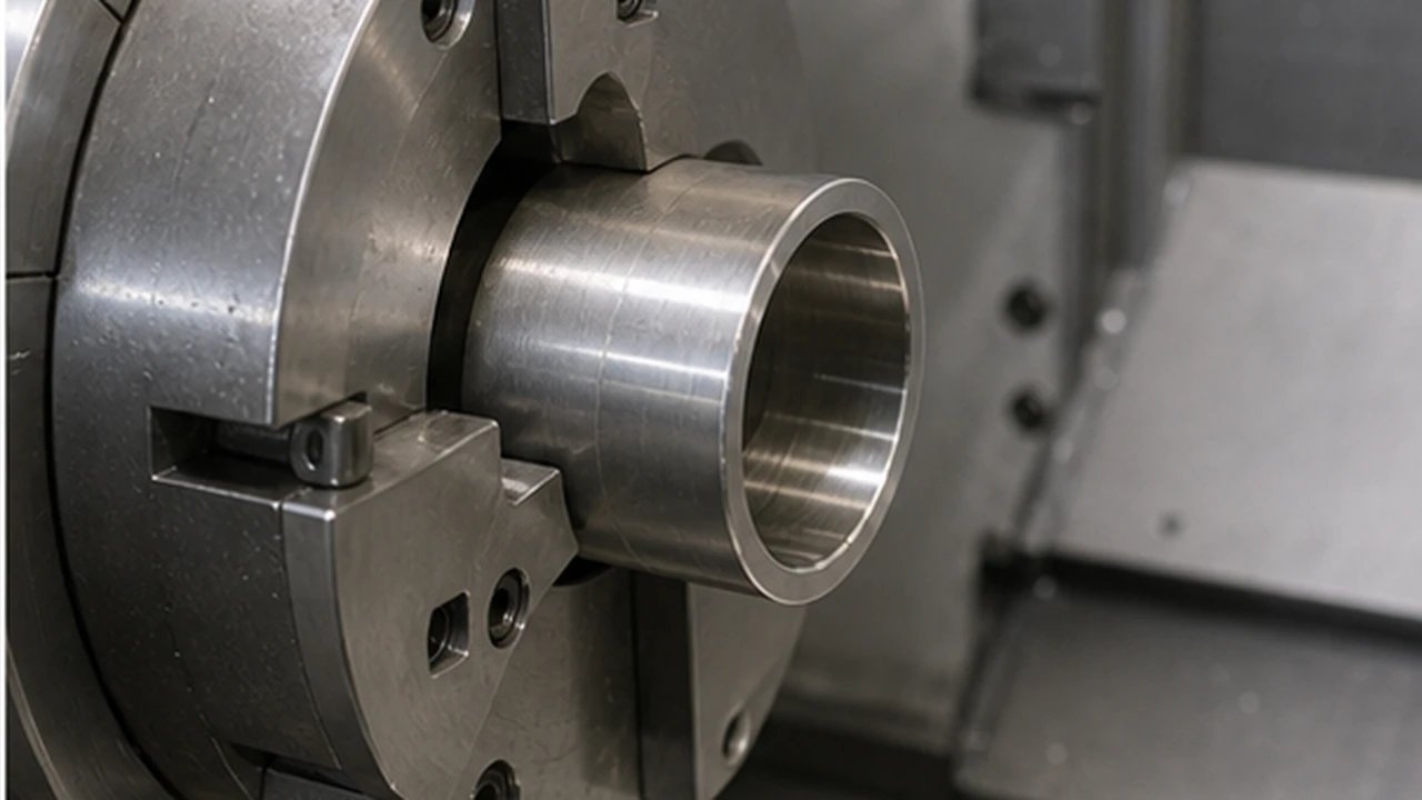
Increase local wall, add a temporary machining ring or move holes away from the thinnest zone when function allows. If geometry cannot change, budget for lower-force workholding and staged cutting. A long sleeve held by a narrow hard jaw can become locally oval. Broad soft jaws or an appropriate mandrel may distribute force, but the selected method must suit the wall and bore. Confirm the shape after release rather than accepting only the clamped reading.
Plan roughing and finishing
Balanced stock removal, cooling and a controlled rest period can reduce movement before the final pass. The route should define when thin features and interrupted cuts are made. Leave enough material for a consistent finishing pass after roughing. Unbalanced removal from one side can release stress unevenly and move the bore. Verify the route on representative stock, particularly after a change in bar condition or supplier.
Inspect without creating the defect
High contact force or unsupported measurement can ovalize a sleeve. Agree the support, orientation, temperature and measurement device, and correlate it with the functional mating part. Use an instrument with suitable contact force and support for the sleeve. Compare readings at several angular positions and axial locations to distinguish size, taper and ovality. Record the free-state or restrained condition with the result so both parties interpret it consistently.
Control edges and hidden intersections
State which edges require a break and which must remain sharp for seating. For cross holes, require removal of loose burrs inside the bore and define an inspection method. Avoid aggressive tumbling where it can round a thin seating edge or damage a close-fitting bore. Cross-hole burrs may require targeted access and magnified inspection. Retain acceptance examples of permitted edge condition and reject loose material inside the passage.
Frequently asked questions
Why does a sleeve become oval after machining?
Residual stress, heat and clamping release can move a low-stiffness wall.
Is a CMM always the best method?
Not automatically. Probe force, point density and fixturing matter; a suitable bore or air gauge may be more representative for some diameters.
Can polishing correct roundness?
Polishing may change size and texture but is not a controlled correction for geometric distortion.
What should the drawing show?
Minimum wall, free-state condition, datum scheme, roundness/cylindricity only where functional, edge requirements and measurement agreement.
Sources and further reading
Send KEC Tour the relevant drawing and interface requirements for review of the proposed manufacturing route.

Zaid Arshad
Manufacturing Content Author · KEC TourZaid Arshad writes practical manufacturing guides for engineers and sourcing teams evaluating custom fittings, CNC-turned parts, sheet-metal components, stampings and die-cast parts. His articles focus on clearer RFQs, supplier evidence, inspection planning and drawing-to-production decisions.
View author profileRelated engineering guides

Engineering Changes for Custom Metal Assemblies: Control the Cutover
Link revised drawings, purchased parts, work in progress and inspection so a design change reaches the correct production units.
Read article
Burr Direction on Stamped Parts: Put the Functional Edge on the Drawing
Specify the acceptable edge condition and orientation where stamped parts contact seals, wires, hands or mating surfaces.
Read article
How to choose stainless steel grades for non-standard fittings
A practical guide for balancing corrosion resistance, machining stability, pressure use, surface finish, and cost.
Read articleTurn your requirements into a production-ready RFQ.
Share your CAD file, material, critical dimensions, finish and target volume. KEC Tour will review the process route before quoting.