
Thread Gauges for Custom Fittings: Match the Thread and Acceptance Rule
Choose thread gauges by standard, size, pitch and tolerance, then document correct use and calibration status.
 Zaid ArshadManufacturing Content Author · KEC Tour
Identify the thread completely
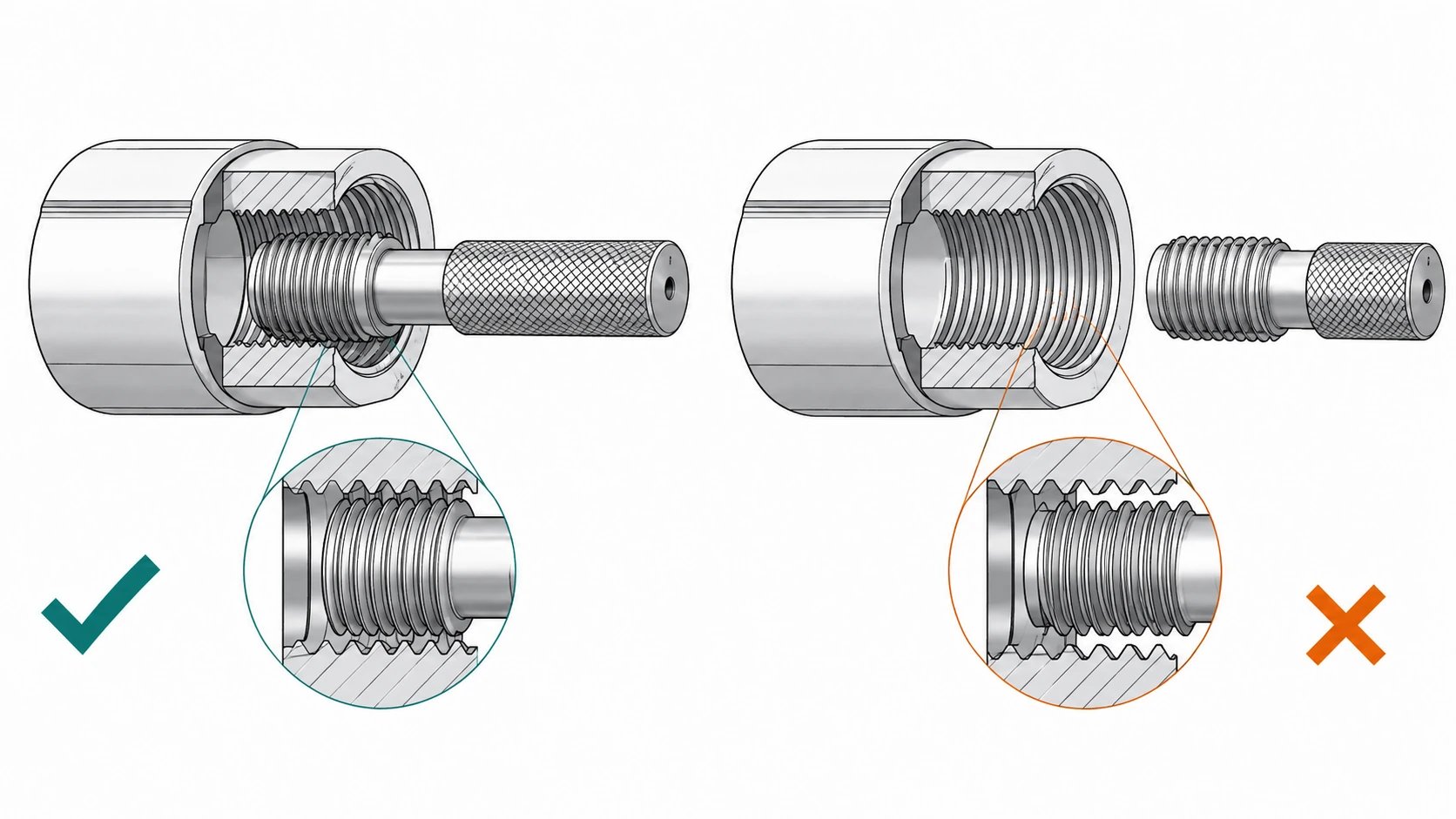
A nominal size and a photograph do not define a thread. Record the standard, size, pitch or threads per inch, thread form, tolerance designation and whether it is parallel or tapered. Similar-looking connections can differ in flank angle, diameter and sealing arrangement. Confirm the mating component and the intended seal before choosing a gauge or using a hand assembly as evidence of conformity.
Select gauges for the requirement
Use the gauge type required by the applicable thread standard and inspection plan. Internal and external threads need different tools, while tapered and parallel threads have different acceptance conventions. A gauge that happens to enter the part is not necessarily the correct gauge. Verify its identification against the drawing and retain that relationship in the setup instructions for repeat production.
Define correct use and interpretation
Follow the applicable standard and gauge manufacturer’s instructions for engagement and rejection criteria. Do not apply a universal number of turns to every thread family. Clean the gauge and part, avoid forcing engagement and control the inspection condition where temperature can affect a close decision. Train inspectors to distinguish a size problem from contamination, damage or a mismatched gauge.
Control gauge condition
A calibrated gauge can still be damaged or contaminated during use. Provide a suitable storage and handling method, periodic verification and a clear response to suspected wear. Record the gauge identity used for acceptance so a later out-of-calibration finding can be assessed against affected production. A calibration sticker alone does not establish that the correct gauge was used or interpreted correctly.
Check the rest of the connection
Thread conformity does not prove that the sealing face, counterbore, wall thickness or mating geometry meets the drawing. Inspect those features separately using appropriate methods. For a pressure connection, functional validation and approved test requirements remain part of the release plan. Keep thread acceptance and leak-test evidence distinct so a failure investigation can identify which interface was actually evaluated.
Approval checklist and evidence
| Review item | Decision to make | Evidence to retain |
|---|---|---|
| Identity | Match thread standard, size, pitch and tolerance. | Complete drawing designation and mating-interface review. |
| Gauge | Select the specified internal or external gauge system. | Gauge identity tied to the applicable acceptance reference. |
| Use | Follow the correct engagement and rejection convention. | Clean, undamaged equipment and trained inspection method. |
| Connection | Inspect sealing geometry separately from thread acceptance. | Final interface results and required functional verification. |
Worked review example
Illustrative scenario: an adapter accepts a mating part by hand, but inspection later shows the drawing and gauge refer to different thread systems. The apparent assembly fit was not a valid acceptance test. The lot is held while the thread identity is resolved against the approved drawing and mating interface. A revised inspection sheet lists the exact gauge designation and acceptance reference, preventing a generic “thread OK” entry from hiding the mismatch.
Information for the engineering review
- Complete thread designation
- Correct gauge type and identity
- Standard-specific acceptance rule
- Cleanliness, wear and calibration
- Separate sealing-interface checks
Discuss this requirement with KEC Tour using the controlled drawing, the relevant mating interfaces and the review information above. Identify the decision that needs confirmation and the acceptance evidence expected with the first parts.
Sources and further reading
Frequently asked questions
Does GO acceptance prove every thread feature?
No. Apply the complete inspection plan, including the relevant rejection checks and other specified dimensions.
Can a mating fitting replace a calibrated gauge?
Only if an approved acceptance method explicitly allows it; informal hand fit is not equivalent.

Zaid Arshad
Manufacturing Content Author · KEC TourZaid Arshad writes practical manufacturing guides for engineers and sourcing teams evaluating custom fittings, CNC-turned parts, sheet-metal components, stampings and die-cast parts. His articles focus on clearer RFQs, supplier evidence, inspection planning and drawing-to-production decisions.
View author profileRelated engineering guides

Engineering Changes for Custom Metal Assemblies: Control the Cutover
Link revised drawings, purchased parts, work in progress and inspection so a design change reaches the correct production units.
Read article
Burr Direction on Stamped Parts: Put the Functional Edge on the Drawing
Specify the acceptable edge condition and orientation where stamped parts contact seals, wires, hands or mating surfaces.
Read article
How to choose stainless steel grades for non-standard fittings
A practical guide for balancing corrosion resistance, machining stability, pressure use, surface finish, and cost.
Read articleTurn your requirements into a production-ready RFQ.
Share your CAD file, material, critical dimensions, finish and target volume. KEC Tour will review the process route before quoting.