
Threaded Fitting Sealing Faces: How to Reduce Leak and Assembly Risk
Define sealing faces, groove geometry, surface condition and final inspection to reduce leaks and assembly problems in threaded fittings.
 Zaid ArshadManufacturing Content Author · KEC Tour

What to specify for this part
| Control point | Define in the RFQ | Risk if omitted |
|---|---|---|
| Seal type | Thread, face, cone, gasket or O-ring | Wrong surface is treated as cosmetic |
| Surface requirement | Finish, waviness, damage and cleanliness | A dimensionally correct part can still leak |
| Transition | Thread runout, relief and edge break | Burrs cut seals or prevent seating |
| Verification | Gauge, profile, visual and leak/assembly test | One test is expected to prove every failure mode |
Map the load and leak path
Draw the path from tightening torque through the contact surface to the contained fluid or gas. Mark which surfaces locate, which clamp and which seal. This prevents an attractive but functionally incomplete drawing. A threaded nut may supply clamping force while an O-ring provides the fluid barrier. In that case the thread is not the sealing surface. Mark the groove, contact land and assembly stop so inspection addresses the actual mechanism.
Specify functional surfaces deliberately
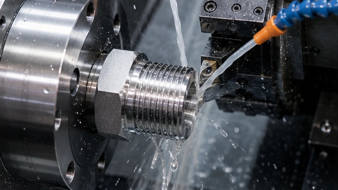
Use a surface-finish requirement only where it protects sealing or motion. Define permissible tool marks, dents and handling damage on sealing faces, and specify edge breaks without rounding away a functional land. An average roughness value does not describe every scratch or directional tool mark. A single groove crossing a sealing land can provide a leak path despite an acceptable average reading. Specify the measurement direction and defect limits from the selected seal design.
Treat burr control as a process step
Internal cross holes, thread starts and relief grooves can retain burrs. State whether sharp edges must be broken, whether passages require cleaning and how hidden intersections will be inspected. Inspect a cross-hole where the drill exits into the internal bore. Cleaning removes loose chips but may leave an attached burr that breaks free later. Select a deburring method that reaches the intersection without changing the seal land or thread start.
Validate the assembly, not only the part
A controlled dimensional report is necessary, but a prototype build can reveal torque, orientation, gasket compression and mating-component variation that isolated inspection cannot. Use representative mating components and seals, including their dimensional variation. Record assembly method and acceptance criteria before testing. A successful demonstration on one hand-selected pair is insufficient evidence for an uncontrolled production combination.
Frequently asked questions
Does a smoother surface always seal better?
No. The required texture depends on seal design and material; over-finishing can add cost without solving geometry or damage issues.
Should leak testing be on every part?
That depends on risk, process capability and agreement. Define test medium, pressure, dwell time and acceptance criteria if testing is required.
Can passivation fix a damaged sealing face?
No. Passivation is a chemical surface treatment; it does not repair dents, burrs or geometric errors.
What is the best first-sample check?
Combine thread gauging, critical dimensions, visual inspection of sealing surfaces and assembly or leak testing under defined conditions.
Sources and further reading
Send KEC Tour the relevant drawing and interface requirements for review of the proposed manufacturing route.

Zaid Arshad
Manufacturing Content Author · KEC TourZaid Arshad writes practical manufacturing guides for engineers and sourcing teams evaluating custom fittings, CNC-turned parts, sheet-metal components, stampings and die-cast parts. His articles focus on clearer RFQs, supplier evidence, inspection planning and drawing-to-production decisions.
View author profileRelated engineering guides

Engineering Changes for Custom Metal Assemblies: Control the Cutover
Link revised drawings, purchased parts, work in progress and inspection so a design change reaches the correct production units.
Read article
Burr Direction on Stamped Parts: Put the Functional Edge on the Drawing
Specify the acceptable edge condition and orientation where stamped parts contact seals, wires, hands or mating surfaces.
Read article
How to choose stainless steel grades for non-standard fittings
A practical guide for balancing corrosion resistance, machining stability, pressure use, surface finish, and cost.
Read articleTurn your requirements into a production-ready RFQ.
Share your CAD file, material, critical dimensions, finish and target volume. KEC Tour will review the process route before quoting.